|
WORK
SAMPLES
|
 |
|
|
BALSA WOOD BRIDGE WRITE-UP
This major assignment this semester in Survey of Engineering Academy was the balsa wood bridge which corresponded to what we were learning in the physics portion of the class. We were to design a bridge in AutoCAD and later build it and test it. We did not just jump into this project by any means. Not only were we learning about basic stresses within a bridge in physics we were also did experimentation before designing our own bridges. Experimentation consisted of groups of three testing different parts of the balsa wood bridge, for instance one group tested type of glue versus the weight it could hold. When we had a basic understanding of bridge construction and the materials we were using, we designed our bridges on the computer with the aid of AutoCAD. Once this was accomplished which was no small feat, we used our AutoCAD drawings to construct the bridge. After this we went onto testing.
The goal of this project was to design and create a balsa wood bridge that could carry the maximum weight possible. Bridges would be judged on appearance, neatness, accurate specifications and of course how much the bridge held. We could use only the materials provided, six square inches of balsa wood and 2/3 oz. of wood glue. They must also must fit within some stringent dimensional specifications: 250mm to 300mm long, 50mm to 75mm wide and less than 100mm tall. In addition a 50mm by 50mm block must be able to fit through the center of the bridge. As well as these specifications, there were certain rules like not being able to split or laminate the wood.
When I embarked on this project my first idea was to build an arch bridge. The arch in naturally strong and is widely used. But I discarded this idea due to it being good in theory but too hard to build and might not be effective with balsa wood. The arch is hard to make and I thought by bending the wood it might weaken it. By doing an easier design I would be able to spend more time on craftsmanship and the details of the bridge. After looking at projects of previous classes, I decided to build a triangle bridge. It was relatively easy to build and was proven to hold a lot of weight. The only problem as opposed to an arch bridge was the joint at the top of the sidewalls would be under a lot of stress. This, however, could be helped with easy reinforcements but would always be an area of concern. My other consideration was a trapezoidal bridge but I dismissed this design because it had three joints in the sidewalls that I would have to reinforce instead of one thus making a triangular bridge a simpler and hopefully better solution.
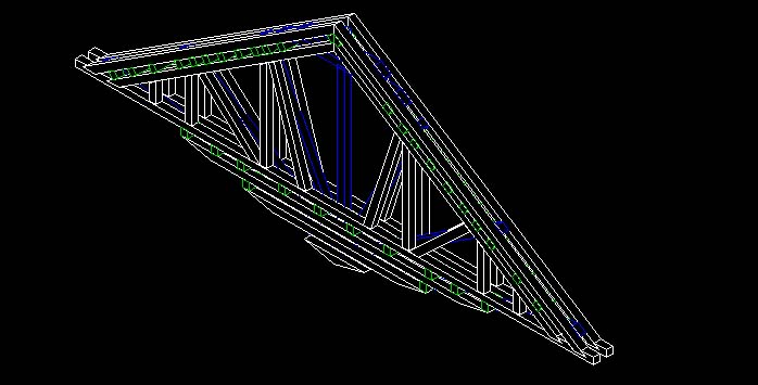
Once I decided on the triangular design I went to work designing it in AutoCAD. Since each group member had to design his own bridge, my partner went to work on designing a trapezoidal bridge while I designed the triangle. I decided to make my bridge as short as possible because it would leave me with more materials and there would be less leverage multiplying the forces within the bridge. I made it as tall as possible to get leverage working for me. Taller designs are better because they can hold the forces of tension and compression within the bridge. I also made it as wide as possible, I did this because the wider it is the more resistant it is to "potato chipping"(sidewalls bend due to stress). The sidewalls were constructed in a three-layer design that we (our class) referred to as a sandwich. The outside layers or the bread layers would be the basic triangular shape with braces supporting it. Both outside layers were to be identical. The inside layer or the meat layer would consist of radial spokes to give it rigidity and braces at each of the three corners to keep them from separating. I would also utilize the allowed under hang and have the spokes connect down there. This made them much more effective and supported the whole sidewall because they would connect away from the loading point. Also I ran the spokes so they would run past the base at the bridge abutment to further strengthen it. The three sides of the triangular sidewall had two pieces of balsa wood running parallel to each other and had a toothpick layer (go only through the sandwich i.e. one sidewall) going through them. This increased lateral and horizontal strength. The structure where the weight was hung on the bridge I reinforced highly because I did not want to build a strong bridge just to have the weight support ripped out of it. Everywhere balsa wood butted up against each other I notched because our previous testing showed it greatly increased the joints strength. As well as all of this, I knew I needed to make the bridge symmetrical so the bridge wouldnt just fall over to the weaker side.
Once my partner and I finished designing our bridges with the aid of AutoCAD we carefully looked over each others and decided to build my bridge because we believed it would hold more weight. This process went very easily because both my partner and I immediately agreed. There were no compromises made because we build the bridge right to specifications, my partner liked my design.
My first attempt at designing my bridge in AutoCAD was fatal because when trying to bring the bread layers and meat layer together for the sidewall they did not line up and I had to scratch it and start over. Since this was the first thing I designed in AutoCAD there were many obstacles I would have to overcome. The hardest thing was trying to work in 3d on a 2d screen. I had difficulty trying to pedit many of the pieces, I relized when I went into a 3d view I was building some of the points on different planes so I corrected this and was able to pedit. Another one of the problems was subtracting the notches in all the pieces. I first tried to make the piece of balsa wood in 2d with the notches in it then extrude the piece but it would not pedit. So I overcame this by building the piece of balsa wood then making the shape of the notch, put that on the balsa wood piece then subtract it. When I finally finished designing the bridge I checked the mass properties and it was .5 square inches over. I fixed this by deleting some of the toothpick pieces and eliminating some of the base where the weight is supported. I learned a lot about AutoCAD through designing this bridge. During the actual construction of the bridge obstacles that needed to be overcome were minimal. Although we did waste a few pieces trying to get the art of notching down. Also I found it difficult to get the exact angles of the joints. This was all overcome through practice and persistence.
An enormous amount of knowledge was accumulated through doing this project. I learned about basic bridge design and what happens to each part of the bridge when stresses are applied. The stresses within the bridge always want to take the path of least resistance meaning the weakest part of the bridge will fail first. The bridge is only as strong as it weakest parts thus you need to make the whole bridge strong. Building, designing and testing the bridges helped me greatly understand what we are doing in physics by actually being able to see it in real life. Also designing something of my own in AutoCAD taught me how to visualize my bridge in a computer program. I learned how to make the sidewall strong and about a phenomenon such as "potato chipping". "Potato chipping" is when the sidewalls bend and look like a potato chip due to excessive force. Also I learned generally in a bridge the top is under compression, the bottom and the vertical braces are under tension.
I was happy with the way the project turned out. It did not look as pretty as I would have hoped but it performed well. The bridge was disqualified however due to the 50mm by 50mm block not being able to fi through it by just a couple of millimeters. It is discouraging to build a whole bridge and have it disqualified by a couple of millimeters. The bridge however performed quite well supporting 135lbs. Within the first 10 lbs placed of the bridge all the deflection it was going to show showed. I kept adding the weight and no signs of stress were shown up until it broke. The bridge broke without warning and if this were an actual bridge this would not be good because you want warning before the bridge breaks. The bridge failed in the sidewalls. They broke right in the middle of one side. I suspect first the top support broke then the bottom. I was happy with this because none of the joints failed.
Our group dynamic was very good. There were no conflicts that needed to be resolved, and we worked together very well. My responsibilities in the group were to design and help construct the bridge. Gabe, my teammate, did the majority of the sidewall construction, but I of course helped. I took the bridge home and connected the sidewalls and built the loading platform. My specific responsibilities were designing and helping in the construction. Gabe looked over my design in AutoCAD and showed me where there were problems.
If I were to do this project again there are many things I would do differently. First and foremost I would make sure I fit the dimensional requirement and not get disqualified by a couple of millimeters. In AutoCAD I would not build it exactly to specification, I would give it a little extra room giving me room for error in construction. I also would have made it shorter in height to give me more materials to work with. The bridge failed in the sidewall so I would have strengthened them by maybe making them three pieces wide rather than two. Also I would like to have made it a little longer so more of the bridge was on the testing apparatus. The craftsmanship on the bridge left something to be desired judging by the reactions of the class, but I disagree. All the joints lined up perfectly and it went together real well. The through pieces on the loading platform went past the sidewalls on purpose but this was mistaken as poor craftsmanship. I did this so the weight would not be focused on the very end of the wood and if it shifted the pieces would still be perfectly supported. But the thing I would change is not having so much excess glue and making sure the pieces of the loading platform were straighter. When this project was completed I had a much better understanding of bridge design than when I started. I was very impressed with how one ounce of material held 135lbs.